Platform
OpenQL supports various target platforms. These platforms can be software simulators or architectures targetting hardware quantum computers. The following platforms are supported by OpenQL:
- software simulator platforms
- hardware platforms
| Note: | Quantumsim and QX are not really platforms. They are means to simulate a particular (hardware) platform. Qasm files for use by QX and python scripts to interface to quantumsim are generated for any hardware platform under the control of options. See the descriptions of the QX and Quantumsim platforms referred to above. |
|---|---|
| Note: | We are planning to use DQCsim, a platform to connect to simulators. In that context, software simulator platforms are connected to by DQCsim, and OpenQL just provides compilation support to a particular hardware platform. |
A platform can be created in OpenQL by using the Platform() API as shown below:
platform = ql.Platform('<platform_name>', <path_to_json_config_file>)
For example,
a platform with the name CCL_platform and using hardware_config_cc_light.json as platform configuration file
can be created as:
platform = ql.Platform('CCL_platform', 'hardware_config_cc_light.json')
Platform Configuration File
The platform configuration file describes the target platform in JSON format. The information in this file is used by all platform independent compiler passes. The parameterization by this information makes these platform independent compiler passes in source code independent of the platform but in effective function dependent on the platform.
A platform configuration file consists of several sections (in arbitrary order) which are described below.
Most of these are mandatory; the specification of the topology and the resources sections are optional.
For example (the ... contains the specification of the respective section):
1 2 3 4 5 6 7 8 9 10 11 12 13 14 15 16 17 18 19 20 21 22 23 24 25 26 27 28 29 30 | {
"eqasm_compiler" : "cc_light_compiler",
"hardware_settings":
{
"qubit_number": 7,
"cycle_time" : 20,
...
},
"topology":
{
...
},
"resources":
{
...
},
"instructions":
{
...
},
"gate_decomposition":
{
...
}
}
|
The platform comfiguration file for its structure is platform independent. It can be extended at will with more sections and more attributes for platform dependent purposes.
The sections below describe sections and attributes that are used by platform independent compiler passes.
Please refer to the sections of the specific platforms for full examples and for the description of any additional attributes.
Attribute eqasm_compiler
The eqasm_compiler attribute specifies the backend compiler to be used for this platform.
After the passes of the platform independent compiler have been called,
the platform independent compiler switches out to the backend compiler to run the platform dependent passes.
The specification of this attribute is mandatory.
The eqasm_compiler attribute can take the following values; these correspond to the platforms that are supported:
none: no backend compiler is calledqx: no backend compiler is called; see above how to generate a qasm file for QXcc_light_compiler: backend compiler for CC_Lighteqasm_backend_cc: backend compiler for CCqumis_compiler: backend compiler to CBOX
Section hardware_settings
The hardware_settings section specifies various parameters describing the platform.
These include the qubit_number'' and ``cycle_time which are generally used,
and the buffer delays, only used by the rcscheduler,
which are related to control electronics in the experiments (for hardware backends).
The specification of this section is mandatory.
For example:
1 2 3 4 5 6 7 8 9 10 11 12 13 14 15 | "hardware_settings":
{
"qubit_number": 7,
"cycle_time" : 20,
"mw_mw_buffer": 0,
"mw_flux_buffer": 0,
"mw_readout_buffer": 0,
"flux_mw_buffer": 0,
"flux_flux_buffer": 0,
"flux_readout_buffer": 0,
"readout_mw_buffer": 0,
"readout_flux_buffer": 0,
"readout_readout_buffer": 0
}
|
In this:
qubit_numberindicates the number of (real) qubits available in the platform. Gates and instructions that addresss qubits do this by providing a qubit index in the range of 0 to qubit_number-1. Using an index outside this range will raise an error.cycle_timeis the clock cycle time. As all other timing specifications in the configuration file it is specified in nanoseconds. Only at multiples of this cycle time, instructions can start executing. The schedulers assign a cycle value to each gate, which means that that gate can start executing a number of nanoseconds after program execution start that equals that cycle value multiplied by the clock cycle_time value.- The other entries of the
hardware_settingssection specify various buffer times to be inserted between various operations due to control electronics setup. For example,mw_mw_buffercan be used to specify time to be inserted between a microwave operation followed by another microwave operation. See Scheduling for details.
Section topology
Specifies the qubit topology as the connection graph of the qubits of the platform. This is primarily used by the mapping pass; this section is optional. It specifies the mapping of qubit indices to qubit positions in the platform, as well as the mapping of connection indices to connections in the platform. A connection is a directed connection in the platform between a pair of qubits that supports qubit interaction. It is directed to distinguish the control and target qubits of two-qubit gates. In a platform topology’s connection graph, qubits are the nodes, and connection are the edges.
It looks like (the ... contains further specifications):
1 2 3 4 5 6 7 8 9 10 11 12 13 14 15 | "topology" :
{
"x_size": 5,
"y_size": 3,
"qubits":
[
{ "id": 0, "x": 1, "y": 2 },
...
],
"edges":
[
{ "id": 0, "src": 2, "dst": 0 },
...
]
},
|
The topology section starts with
the specification of the two dimensions of a rectangular qubit grid by specifying x_size and y_size.
The positions of the real qubits of the platform are defined relative to this (artificial) grid.
The coordinates in the X direction are 0 to x_size-1.
In the Y direction they are 0 to y_size-1.
Next, for each available qubit in the platform, its position in the grid is specified:
the id specifies the particular qubit’s index, and x and y specify its position in the grid,
as coordinates in the X and Y direction, respectively.
Please note that not every position in the x_size by y_size grid needs to correspond to a qubit.
Qubits are connected in directed pairs, called edges.
Edge indices form a contigous range starting from 0.
Each edge in the topology is given an id which denotes its index, and a source (control) and destination (target) qubit index by src and dst, respectively. This means that there can be edges between the same pair of qubits but in opposite directions.
The qubit indices specified here must correspond to available qubits in the platform.
For a full example of this section, please refer to CC-Light Platform.
Section resources
Specify the classical control constraints of the platform. This section is optional. These constraints are used by the resource manager, that on its turn is used by the scheduling and mapping passes. These classical control constraints are described as restrictions on concurrent access to resources of predefined resource types. Specification of these resources affects scheduling and mapping of gates.
The resources section specifies zero or more resource types
that are predefined by the mandatory platform dependent resource manager.
For CC-Light, these resource types are qubits, qwgs, meas_units, edges, and detuned_qubits.
The presence of one in the configuration file
indicates that the resource-constrained scheduler should take it into account
when trying to schedule operations in parallel, i.e. with overlapping executions.
Although their names suggest otherwise, they are just vehicles to configure the scheduler
and need not correspond to real resources present in the hardware.
This also implies that they can be easily reused for other platforms.
For a full example of this section, including an extensive description of the various resource types, please refer to CC-Light Platform. For a description of their use by the scheduler, please refer to Scheduling.
Section instructions
Specifies the list of primitive gates supported by the platform. Creation of a primitive custom gate takes its parameters from this specification to initialize the gate’s attributes.
Examples of a 1-qubit and a 2-qubit instruction are shown below:
1 2 3 4 5 6 7 8 9 10 11 12 13 14 15 16 17 18 19 20 21 22 23 24 25 | "instructions": {
"x q0": {
"duration": 40,
"latency": 0,
"qubits": ["q0"],
"matrix": [ [0.0,0.0], [1.0,0.0],
[1.0,0.0], [0.0,0.0]
],
"disable_optimization": false,
"type": "mw"
},
"cnot q2,q0": {
"duration": 80,
"latency": 0,
"qubits": ["q2","q0"],
"matrix": [ [0.1,0.0], [0.0,0.0], [0.0,0.0], [0.0,0.0],
[0.0,0.0], [1.0,0.0], [0.0,0.0], [0.0,0.0],
[0.0,0.0], [0.0,0.0], [0.0,0.0], [1.0,0.0],
[0.0,0.0], [0.0,0.0], [1.0,0.0], [0.0,0.0],
],
"disable_optimization": true,
"type": "flux"
},
...
}
|
x q0 is the name of the instruction which will be used to refer to this
instruction inside the OpenQL program. x would also be allowed as name. The former defines a specialized gate, the latter defines a generalized gate; please refer to Quantum Gates for the definitions of these terms and to Input external representation for the use of these two forms of instruction definitions.
durationspecifies the time duration required to complete this instruction.latency; due to control electronics, it is sometimes required to add a positive or negative latency to an instruction. This can be specified by thelatencyfield. This field is divided by cycle time and rounded up to obtain an integer number of cycles. After scheduling is performed, an instruction is shifted back or forth in time depending upon the calculated cycles corresponding to the latency field.qubitsrefer to the list of qubit operands.Note: This field has to match the operands in the name of the instruction, if specified there. This is checked. Otherwise there is no use of this field. So there is redundancy here. matrixspecifies the process matrix representing this instruction. If optimization is enabled, this matrix will be used by the optimizer to fuse operations together, as discussed in Optimization. This can be left un-specified if optimization is disabled.disable_optimizationis used to enable/disable optimization of this instruction. Settingdisable_optimizationtotruewill mean that this instruction cannot be compiled away during optimization.Note: This is not implemented. Propose to do so. Then have to define what is exactly means: compiling away is interpreted as the gate with this flag truewill never be deleted from a circuit once created, nor that the circuit that contains it will be deleted.typeindicates whether the instruction is a microwave (mw), flux (flux) or readout (readout). This is used in CC-Light by the resource manager to select the resources of a gate for scheduling.
Section gate_decomposition
Specifies a list of gates defined by decomposition into primitive gates.
Examples of two decompositions are shown below.
%0 and %1 refer to the first argument and the second argument. This means
according to the decomposition on Line 2, rx180 %0 will allow us to
decompose rx180 q0 to x q0. Similarly, the decomposition on Line 3 will
allow us to decompose cnot q2, q0 to three instructions, namely:
ry90 q0, cz q2, q0 and ry90 q0.
1 2 3 4 | "gate_decomposition": {
"rx180 %0" : ["x %0"],
"cnot %0,%1" : ["ry90 %1","cz %0,%1","ry90 %1"]
}
|
These decompositions are simple macros (in-place substitutions) which allow programmer to manually specify a decomposition. These take place at the time of creation of a gate in a kernel. This means the scheduler will schedule decomposed instructions. OpenQL can also perform Control and Unitary decompositions which are discussed in Decomposition.
QX Platform
Details of the configuration file for the QX simulator platform. [TBD]
The OpenQL compiler is able to generate a qasm file to interface to QX. This qasm file generation is controlled by option write_qasm_files:
- yes: Qasm files are generated before and after most of the passes.
- no: No qasm files are generated.
The qasm files are generated in the default output directory. The qasm file to be used for QX is named by the program name suffixed with .qasm.
Unlike in previous releases, quantumsim is not considered a platform. It is a means to simulate a particular (hardware) platform without timing.
[TBD]
Quantumsim Platform
The OpenQL compiler is able to generate a python script to interface to quantumsim. This script generation is controlled by option quantumsim:
- no: No script to interface to quantumsim is generated.
- yes: A python script is generated to interface with a standard version of quantumsim.
- qsoverlay: A python script is generated to interface with the qsoverlay module on top of quantumsim.
The scripts are generated in the default output directory.
Unlike in previous releases, quantumsim is not considered a platform. It is a means to simulate a particular (hardware) platform.
The quantumsim option is checked in the CC-Light backend in two places:
- just when entering the backend after decomposition before scheduling
- just before generating QISA, i.e. after mapping, rcscheduling and decomposition after scheduling.
[TBD]
CC-Light Platform
The file hardware_configuration_cc_light.json
available inside the tests directory is an example configuration file for
the CC-Light platform with 7 qubits.
This file consists of several sections (in arbitrary order) which are described below.
eqasm_compiler specifies the backend compiler to be used for this CC-Light platform,
which in this case has the name cc_light_compiler.
The backend compiler is called after the platform independent passes, and calls several private passes by itself.
This backend compiler and its passes are described in detail in Compiler Passes.
One of these is the code generation pass.
"eqasm_compiler" : "cc_light_compiler",
hardware_settings is used to configure various
hardware settings of the platform as shown below. These settings affect the
scheduling of instructions. Please refer to Platform for a full description and an example.
topology specifies the mapping of qubit indices to qubit positions in the platform, as well as the mapping of connection indices to connections in the platform.
A connection is a directed connection in the platform between a pair of qubits that supports qubit interaction.
It is directed to distinguish the control and target qubits of two-qubit gates.
In a platform topology’s connection graph, qubits are the nodes, and connection are the edges.
Figure Fig. 1 shows these numberings in the 7 qubit CC-Light platform.
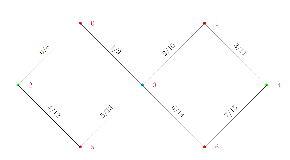
Fig. 1 Connection graph with qubit and connection (edge) numbering in the 7 qubits CC-Light Platform
The topology section starts with
the specification of the two dimensions of a rectangular qubit grid by specifying x_size and y_size.
The positions of the real qubits of the platform are defined relative to this (artificial) grid.
The coordinates in the X direction are 0 to x_size-1.
In the Y direction they are 0 to y_size-1.
Next, for each available qubit in the platform, its position in the grid is specified:
the id specifies the particular qubit’s index, and x and y specify its position in the grid,
as coordinates in the X and Y direction, respectively.
Please note that not every position in the x_size by y_size grid needs to correspond to a qubit.
Qubits are connected in directed pairs, called edges.
Edge indices form a contigous range starting from 0.
Each edge in the topology is given an id which denotes its index, and a source (control) and destination (target) qubit index by src and dst, respectively. This means that although Edge 0 and Edge 8 are
between qubit 0 and qubit 2, they are different as these edges are in opposite directions.
The qubit indices specified here must correspond to available qubits in the platform.
1 2 3 4 5 6 7 8 9 10 11 12 13 14 15 16 17 18 19 20 21 22 23 24 25 26 27 28 29 30 31 32 33 | "topology" : {
"x_size": 5,
"y_size": 3,
"qubits":
[
{ "id": 0, "x": 1, "y": 2 },
{ "id": 1, "x": 3, "y": 2 },
{ "id": 2, "x": 0, "y": 1 },
{ "id": 3, "x": 2, "y": 1 },
{ "id": 4, "x": 4, "y": 1 },
{ "id": 5, "x": 1, "y": 0 },
{ "id": 6, "x": 3, "y": 0 }
],
"edges":
[
{ "id": 0, "src": 2, "dst": 0 },
{ "id": 1, "src": 0, "dst": 3 },
{ "id": 2, "src": 3, "dst": 1 },
{ "id": 3, "src": 1, "dst": 4 },
{ "id": 4, "src": 2, "dst": 5 },
{ "id": 5, "src": 5, "dst": 3 },
{ "id": 6, "src": 3, "dst": 6 },
{ "id": 7, "src": 6, "dst": 4 },
{ "id": 8, "src": 0, "dst": 2 },
{ "id": 9, "src": 3, "dst": 0 },
{ "id": 10, "src": 1, "dst": 3 },
{ "id": 11, "src": 4, "dst": 1 },
{ "id": 12, "src": 5, "dst": 2 },
{ "id": 13, "src": 3, "dst": 5 },
{ "id": 14, "src": 6, "dst": 3 },
{ "id": 15, "src": 4, "dst": 6 }
]
},
|
These mappings are used in:
- the QISA, the instruction set of the platform, notably in the instructions that set the masks stored in the mask registers that are used in the instructions of two-qubit gates to address the operands.
- the mapper pass that maps virtual qubit indices to real qubit indices. It is described in detail in Mapping.
- the postdecomposition pass that maps two-qubit flux instructions to sets of one-qubit flux instructions.
resources is the section that is used to specify/configure various resource types available
in the platform as discussed below. Specification of these resource types affects
scheduling and mapping of gates. The configuration of the various resource types
in hardware_configuration_cc_light.json
assumes that the CC-Light architecture has the following relations between devices, connections, qubits and operations:
| Device Name | DIO connector | Target qubits | Operation Type |
|---|---|---|---|
| UHFQC-0 | DIO1 | 0, 2, 3, 5, 6 | measurement |
| UHFQC-1 | DIO2 | 1, 4 | measurement |
| AWG-8 0, channel 0~6 | DIO3 | 0~6 | flux |
| AWG-8 1, channel 0 | DIO4 | 0,1 | microwave |
| AWG-8 1, channel 1 | DIO4 | 5,6 | microwave |
| AWG-8 2, channel 0 | DIO5 | 2,3,4 | microwave |
| VSM | – | 0~6 | microwave masking |
The resources section specifies zero or more resource types.
Each of these must be predefined by the platform’s resource manager.
For CC-Light, these resource types are qubits, qwgs, meas_units, edges and detuned_qubits.
The presence of one in the configuration file
indicates that the resource-constrained scheduler should take it into account
when trying to schedule operations in parallel, i.e. with overlapping executions;
absence of one in the configuration file thus indicates that this resource is ignored by the scheduler.
Although their names suggest otherwise, they are just vehicles to configure the scheduler
and need not correspond to real resources present in the hardware.
qubits: That one qubit can only be involved in one operation at each particular cycle,
is specified by the qubits resource type, as shown
below. count needs to be at least the number of available qubits.
1 2 3 4 | "qubits":
{
"count": 7
},
|
So, when this resource type is included in the configuration in this way, it will guarantee that the resource-constrained scheduler will never schedule two operations in parallel when these share a qubit index in the range of 0 to count-1 as operand.
qwgs: This resource type specifies, when configured, several sets of qubit indices.
For each set it specifies that when one of the qubits in the set is in use in a particular cycle
by an instruction of ‘mw’ type (single-qubit rotation gates usually),
that when one of the other qubits in the set is in use by an instruction of ‘mw’ type,
that instruction must be doing the same operation.
In CC-light, this models QWG wave generators that only can generate one type of wave at the same time,
and in which each wave generator is connected through a switch to a subset of the qubits.
1 2 3 4 5 6 7 8 9 10 | "qwgs" :
{
"count": 3,
"connection_map":
{
"0" : [0, 1],
"1" : [2, 3, 4],
"2" : [5, 6]
}
},
|
The number of sets (waveform generators) is specified by the count field. In
the connection_map it is specified which waveform generator is connected to which qubits.
Each qubit that can be used by an instruction of ‘mw’ type,
should be specified at most once in the combination of sets of connected qubits.
For instance, the line with "0" specifies that qwg 0 is connected to
qubits 0 and 1. This is based on the AWG-8 1, channel 0 entry in
Table Table 1. This information is utilized by the
scheduler to perform resource-constraint aware scheduling of gates.
meas_units: This resource type is similar to qwgs; the difference is
that it is not constraining on the operations to be equal
but on the start cycle of measurement to be equal.
It specifies, when configured, several sets of qubit indices.
For each set it specifies that when one of the qubits in the set is in use in a particular cycle
by an instruction of ‘readout’ type (measurement gates usually)
that when one of the other qubits in the set is in use by an instruction of ‘readout’ type
the latter must also have started in that cycle.
In CC-light, this models measurement units that each can only measure multiple qubits at the same time
when the measurements of those qubits start in the same cycle.
There are count number of sets (measurement units). For each
measurement unit it is described which set of qubits it controls.
Each qubit that can be used by an instruction of ‘readout’ type,
should be specified at most once in the combination of sets of connected qubits.
1 2 3 4 5 6 7 8 9 | "meas_units" :
{
"count": 2,
"connection_map":
{
"0" : [0, 2, 3, 5, 6],
"1" : [1, 4]
}
},
|
edges: This resource type specifies, when present, for each directed qubit pair corresponding
to a directed connection in the platform (edge), which set of other edges
cannot execute a two-qubit gate in parallel.
Two-qubit flux gates (instructions of flux type) are controlled by
qubit-selective frequency detuning. Frequency-detuning may cause neighbor
qubits (qubits connected by an edge) to inadvertently engage in a two-qubit flux
gate as well. This happens when two connected qubits are both executing a
two-qubit flux gate. Therefore, for each edge executing a two-qubit gate,
certain other edges should not execute a two-qubit gate.
Edges and the constraints imposed by these edges are specified in the edges section.
count specifies at least the number of edges between qubits in the platform.
connection_map specifies connections.
For example, the entry with “0” specifies for Edge 0 a constraint on Edge 2 and Edge 10.
This means, if Edge 0 is in use by a two-qubit flux gate,
a two-qubit flux gate on Edge 2 and Edge 10 will not be scheduled, until the one on Edge 0 completes.
When edges is present as a resource type, each edge of the platform must appear in the connection_map.
Providing an empty list for an edge in the connection_map will result
in not applying any edge constraint during scheduling.
1 2 3 4 5 6 7 8 9 10 11 12 13 14 15 16 17 18 19 20 21 22 23 | "edges":
{
"count": 16,
"connection_map":
{
"0": [2, 10],
"1": [3, 11],
"2": [0, 8],
"3": [1, 9],
"4": [6, 14],
"5": [7, 15],
"6": [4, 12],
"7": [5, 13],
"8": [2, 10],
"9": [3, 11],
"10": [0, 8],
"11": [1, 9],
"12": [6, 14],
"13": [7, 15],
"14": [4, 12],
"15": [5, 13]
}
},
|
detuned_qubits: Constraints on executing two-qubit gates in parallel to other gates,
are specified in this detuned_qubits section, when present.
For each edge, the set of qubits is specified that cannot execute a gate
when on the particular edge a two-qubit gate is executed;
at the same time, this resource type specifies implicitly for each qubit
when it would be executing a gate, on which edges a two-qubit gate cannot execute in parallel.
There are at least count number of qubits involved.
When detuned_qubits is present as a resource type,
each edge of the platform must appear in the connection_map.
Providing an empty set of qubits for an edge in the connection_map will result
in not applying the detuned_qubits constraint related to this edge during scheduling.
Not all qubits need to be involved in this type of constraint with some edge.
In the example below, Qubit 0 and Qubit 1 are examples of qubits executing a gate on which
can be in parallel to executing a two-qubit gate on any pair of qubits.
A two-qubit flux gate lowers the frequency of its source qubit to get near the frequency of its target qubit. Any two qubits which have near frequencies execute a two-qubit flux gate. To prevent any neighbor qubit of the source qubit that has the same frequency as the target qubit to interact as well, those neighbors must have their frequency detuned (lowered out of the way). A detuned qubit cannot execute a single-qubit rotation (an instruction of ‘mw’ type).
1 2 3 4 5 6 7 8 9 10 11 12 13 14 15 16 17 18 19 20 21 22 23 | "detuned_qubits":
{
"count": 7,
"connection_map":
{
"0": [3],
"1": [2],
"2": [4],
"3": [3],
"4": [],
"5": [6],
"6": [5],
"7": [],
"8": [3],
"9": [2],
"10": [4],
"11": [3],
"12": [],
"13": [6],
"14": [5],
"15": []
}
}
|
instructions: Instructions can be specified/configured in the instructions section.
Examples of a 1-qubit and a 2-qubit instruction are shown below:
1 2 3 4 5 6 7 8 9 10 11 12 13 14 15 16 17 18 19 20 21 22 23 24 25 26 27 28 29 30 31 32 33 34 | "instructions": {
"x q0": {
"duration": 40,
"latency": 0,
"qubits": ["q0"],
"matrix": [ [0.0,0.0], [1.0,0.0],
[1.0,0.0], [0.0,0.0]
],
"disable_optimization": false,
"type": "mw",
"cc_light_instr_type": "single_qubit_gate",
"cc_light_instr": "x",
"cc_light_codeword": 60,
"cc_light_opcode": 6
},
"cnot q2,q0": {
"duration": 80,
"latency": 0,
"qubits": ["q2","q0"],
"matrix": [ [0.1,0.0], [0.0,0.0], [0.0,0.0], [0.0,0.0],
[0.0,0.0], [1.0,0.0], [0.0,0.0], [0.0,0.0],
[0.0,0.0], [0.0,0.0], [0.0,0.0], [1.0,0.0],
[0.0,0.0], [0.0,0.0], [1.0,0.0], [0.0,0.0],
],
"disable_optimization": true,
"type": "flux",
"cc_light_instr_type": "two_qubit_gate",
"cc_light_instr": "cnot",
"cc_light_right_codeword": 127,
"cc_light_left_codeword": 135,
"cc_light_opcode": 128
},
...
}
|
Please refer to Platform for a description of the CC-Light independent attributes. The CC-Light dependent attributes are:
cc_light_instr_type is used to
specify the type of instruction based on the number of expected qubits.
Please refer to Scheduling for its use by the rcscheduler.
cc_light_instr specifies the name of this instruction used in CC-Light architecture. This name
is used in the generation of the output code and in the implementation of the checking of the qwg resource.
Please refer to Scheduling for its use by the rcscheduler.
cc_light_codeword, cc_light_right_codeword, cc_light_left_codeword
and cc_light_opcode are used in the generation of the control store file for
CC-Light platform. For single qubit instructions, cc_light_codeword refers
to the codeword to be used for this instruction. Recall that the quantum pipeline
contains a VLIW front end with two VLIW lanes, each lane processing one
quantum operation. cc_light_right_codeword and cc_light_left_codeword
are used to specify the codewords used for the left and right operation in
two-qubit instruction. cc_light_opcode specifies the opcode used for this
instruction.
Warning
At the moment, generation of the control-store file is disabled in the compiler as this was not being used in experiments.
gate_decomposition Gate decompositions can also be specified in the configuration file in the
gate_decomposition section. Please refer to Platform for a description and full example of this section.
Central Controller Platform Configuration
CC configuration file
This section describes the JSON configuration file format for OpenQL in conjunction with the Central Controller (CC) backend. Note that for the CC - contrary to the CC-light - the final hardware output is entirely determined by the contents of the configuration file, there is no built-in knowledge of instrument connectivity or codeword organization.
The CC configuration file consists of several sections described below.
To select the CC backend, the following is required:
"eqasm_compiler" : "eqasm_backend_cc",
resources unused for the CC backend, section may be empty
topology unused for the CC backend, section may be empty
alias unused by OpenQL
hardware_settings is used to configure various
hardware settings of the platform as shown below. These settings affect the
scheduling of instructions. Please refer to Platform for a full description and an example.
The following settings are not used by the CC backend:
- hardware_settings/mw_mw_buffer
- hardware_settings/mw_flux_buffer
- hardware_settings/mw_readout_buffer
- hardware_settings/flux_mw_buffer
- hardware_settings/flux_flux_buffer
- hardware_settings/flux_readout_buffer
- hardware_settings/readout_mw_buffer
- hardware_settings/readout_flux_buffer
- hardware_settings/readout_readout_buffer
All settings related to the CC backend are in section hardware_settings/eqasm_backend_cc of the configuration file. This section is divided into several subsections as shown below.
Instrument definitions
Subsection instrument_definitions defines immutable properties of instruments, i.e. independent of the actual control setup:
1 2 3 4 5 6 7 8 9 10 11 12 13 14 15 16 17 18 | "instrument_definitions": {
"qutech-qwg": {
"channels": 4,
"control_group_sizes": [1, 4],
},
"zi-hdawg": {
"channels": 8,
"control_group_sizes": [1, 2, 4, 8], // NB: size=1 needs special treatment of waveforms because one AWG unit drives 2 channels
},
"qutech-vsm": {
"channels": 32,
"control_group_sizes": [1],
},
"zi-uhfqa": {
"channels": 9,
"control_group_sizes": [1],
}
}, // instrument_definitions
|
Where:
channelsdefines the number of logical channels of the instrument. For most instruments there is one logical channel per physical channel, but the ‘zi-uhfqa’ provides 9 logical channels on one physical channel pair.control_group_sizesstates possible arrangements of channels operating as a vector
Control modes
Subsection control_modes defines modes to control instruments. These define which bits are used to control groups of channels and/or get back measurement results:
1 2 3 4 5 6 7 8 9 10 11 12 13 14 15 16 17 18 19 20 21 22 23 24 25 26 27 28 29 30 31 32 33 34 35 36 37 38 39 40 41 42 43 44 45 46 47 48 49 50 51 52 53 54 55 56 57 58 59 60 | "control_modes": {
"awg8-mw-vsm-hack": { // ZI_HDAWG8.py::cfg_codeword_protocol() == 'microwave'. Old hack to skip DIO[8]
"control_bits": [
[7,6,5,4,3,2,1,0], // group 0
[16,15,14,13,12,11,10,9] // group 1
],
"trigger_bits": [31]
},
"awg8-mw-vsm": { // the way the mode above should have been
"control_bits": [
[7,6,5,4,3,2,1,0], // group 0
[15,14,13,12,11,10,9,8] // group 1
],
"trigger_bits": [31]
},
"awg8-mw-direct-iq": { // just I&Q to generate microwave without VSM. HDAWG8: "new_novsm_microwave"
"control_bits": [
[6,5,4,3,2,1,0], // group 0
[13,12,11,10,9,8,7], // group 1
[22,21,20,19,18,17,16], // group 2. NB: starts at bit 16 so twin-QWG can also support it
[29,28,27,26,25,24,23] // group 4
],
"trigger_bits": [31]
},
"awg8-flux": { // ZI_HDAWG8.py::cfg_codeword_protocol() == 'flux'
// NB: please note that internally one AWG unit handles 2 channels, which requires special handling of the waveforms
"control_bits": [
[2,1,0], // group 0
[5,4,3],
[8,7,6],
[11,10,9],
[18,17,16], // group 4. NB: starts at bit 16 so twin-QWG can also support it
[21,20,19],
[24,23,22],
[27,26,25] // group 7
],
"trigger_bits": [31]
},
"awg8-flux-vector-8": { // single code word for 8 flux channels.
"control_bits": [
[7,6,5,4,3,2,1,0]
],
"trigger_bits": [31]
},
"uhfqa-9ch": {
"control_bits": [[17],[18],[19],[20],[21],[22],[23],[24],[25]], // group[0:8]
"trigger_bits": [16],
"result_bits": [[1],[2],[3],[4],[5],[6],[7],[8],[9]], // group[0:8]
"data_valid_bits": [0]
},
"vsm-32ch":{
"control_bits": [
[0],[1],[2],[3],[4],[5],[6],[7], // group[0:7]
[8],[9],[10],[11],[12],[13],[14],[15], // group[8:15]
[16],[17],[18],[19],[20],[21],[22],[23], // group[16:23]
[24],[25],[26],[27],[28],[28],[30],[31] // group[24:31]
],
"trigger_bits": [] // no trigger
}
}, // control_modes
|
Where:
<key>is a name which can be referred to from key ‘instruments/[]/ref_control_mode’control_bitsdefines G groups of B bits, with:- G determines which the ‘instrument_definitions/<key>/control_group_sizes’ used
- B is an ordered list of bits (MSB to LSB) used for the code word
trigger_bitsvector of bits used to trigger the instrument. Must either be size 1 (common trigger) or size G (separate trigger per group)
FIXME: examples
* result_bits reserved for future use
* data_valid_bits reserved for future use
Signals
Subsection signals provides a signal library that gate definitions can refer to:
1 2 3 4 5 6 7 8 9 10 11 12 13 14 15 16 17 18 19 20 21 22 23 24 25 26 27 | "signals": {
"single-qubit-mw": [
{ "type": "mw",
"operand_idx": 0,
"value": [
"{gateName}-{instrumentName}:{instrumentGroup}-gi",
"{gateName}-{instrumentName}:{instrumentGroup}-gq",
"{gateName}-{instrumentName}:{instrumentGroup}-di",
"{gateName}-{instrumentName}:{instrumentGroup}-dq"
]
},
{ "type": "switch",
"operand_idx": 0,
"value": ["dummy"] // NB: no actual signal is generated
}
],
"two-qubit-flux": [
{ "type": "flux",
"operand_idx": 0, // control
"value": ["flux-0-{qubit}"]
},
{ "type": "flux",
"operand_idx": 1, // target
"value": ["flux-1-{qubit}"]
}
]
}, // signals
|
Where:
<key>is a name which can be referred to from key ‘instructions/<>/cc/ref_signal’. It defines an array of records with the fields below:typedefines a signal type. This is used to select an instrument that provides that signal type through key ‘instruments/*/signal_type’. The types are entirely user defined, there is no builtin notion of their meaning.operand_idxstates the operand index of the instruction/gate this signal refers to. Signals must be defined for all operand_idx the gate refers to, so a 3-qubit gate needs to define 0 through 2. Several signals with the same operand_idx can be defined to select several signal types, as shown in “single-qubit-mw” which has both “mw” (provided by an AWG) and “switch” (provided by a VSM)
valuedefines a vector of signal names. Supports the following macro expansions:
Instruments
Subsection instruments defines instruments used in this setup, their configuration and connectivity.
1 2 3 4 5 6 7 8 9 10 11 12 13 14 15 16 17 18 19 20 21 22 23 24 25 26 27 28 29 30 31 32 33 34 35 36 37 38 39 40 41 42 43 44 45 46 47 48 49 50 51 52 53 54 55 56 57 58 59 60 61 62 63 64 65 66 67 68 | "instruments": [
// readout.
{
"name": "ro_0",
"qubits": [[6], [11], [], [], [], [], [], [], []],
"signal_type": "measure",
"ref_instrument_definition": "zi-uhfqa",
"ref_control_mode": "uhfqa-9ch",
"controller": {
"name": "cc",
"slot": 0,
"io_module": "CC-CONN-DIO"
}
},
// ...
// microwave.
{
"name": "mw_0",
"qubits": [ // data qubits:
[2, 8, 14], // [freq L]
[1, 4, 6, 10, 12, 15] // [freq H]
],
"signal_type": "mw",
"ref_instrument_definition": "zi-hdawg",
"ref_control_mode": "awg8-mw-vsm-hack",
"controller": {
"name": "cc",
"slot": 3,
"io_module": "CC-CONN-DIO-DIFF"
}
},
// ...
// VSM
{
"name": "vsm_0",
"qubits": [
[2], [8], [14], [], [], [], [], [], // [freq L]
[1], [4], [6], [10], [12], [15], [], [], // [freq H]
[0], [5], [9], [13], [], [], [], [], // [freq Mg]
[3], [7], [11], [16], [], [], [], [] // [freq My]
],
"signal_type": "switch",
"ref_instrument_definition": "qutech-vsm",
"ref_control_mode": "vsm-32ch",
"controller": {
"name": "cc",
"slot": 5,
"io_module": "cc-conn-vsm"
}
},
// flux
{
"name": "flux_0",
"qubits": [[0], [1], [2], [3], [4], [5], [6], [7]],
"signal_type": "flux",
"ref_instrument_definition": "zi-hdawg",
"ref_control_mode": "awg8-flux",
"controller": {
"name": "cc",
"slot": 6,
"io_module": "CC-CONN-DIO-DIFF"
}
},
// ...
] // instruments
|
Where:
namea friendly name for the instrumentref_instrument_definitionselects record under ‘instrument_definitions’, which must exits or an error is raisedref_control_modeselects record under ‘control_modes’, which must exits or an error is raisedsignal_typedefines which signal type this instrument instance provides.
qubitsG groups of 1 or more qubits. G must match one of the available group sizes of ‘instrument_definitions/<ref_instrument_definition>/control_group_sizes’. If more than 1 qubits are stated per group - e.g. for an AWG used in conjunction with a VSM - they may not produce conflicting signals at any time slot, or an error is raisedcontroller/slotthe slot number of the CC this instrument is connected tocontroller/namereserved for future usecontroller/io_modulereserved for future use
Additions to section ‘instructions’
The CC backend extends section “instructions/<key>” with a subsection “cc” as shown in the example below:
1 2 3 4 5 6 7 8 9 10 11 12 13 14 15 16 17 18 19 20 21 22 23 24 25 26 27 28 29 30 31 32 33 | "ry180": {
"duration": 20,
"matrix": [ [0.0,1.0], [1.0,0.0], [1.0,0.0], [0.0,0.0] ],
"type": "mw",
"cc_light_instr": "y",
"cc": {
"ref_signal": "single-qubit-mw",
"static_codeword_override": 2
}
},
"cz_park": {
"duration": 40,
"matrix": [ [0.0,1.0], [1.0,0.0], [1.0,0.0], [0.0,0.0] ],
"type": "flux",
"cc_light_instr": "cz",
"cc": {
"signal": [
{ "type": "flux",
"operand_idx": 0, // control
"value": ["flux-0-{qubit}"]
},
{ "type": "flux",
"operand_idx": 1, // target
"value": ["flux-1-{qubit}"]
},
{ "type": "flux",
"operand_idx": 2, // park
"value": ["park_cz-{qubit}"]
}
],
"static_codeword_override": 1
}
}
|
Where:
cc/ref_signalpoints to a signal definition inhardware_settings/eqasm_backend_cc/signals, which must exist or an error is raisedcc/signaldefines a signal in place, in an identical fashion ashardware_settings/eqasm_backend_cc/signalscc/static_codeword_overrideprovides a user defined codeword for this instruction. Currently, this key is compulsory, but in the future, codewords will be assigned automatically to make better use of limited codeword space
The following standard OpenQL fields are used:
<key>name for the instruction. The following syntaxes can be used for instruction names:- “<name>”
- “<name><qubits>”
durationduration in [ns]matrixthe process matrix. Required, but only used if optimization is enabledtypeinstruction type used by scheduler, one of the builtin names “mw”, “flux” or “measure”. Has no relation with signal type definition of CC backend, even though we use the same string values therecc_light_instrrequired by scheduler.
latencyoptional instruction latency in [ns], used by schedulerqubitsoptional
The following fields in ‘instructions’ are not used by the CC backend:
cc_light_instr_typeFIXME: is used in scheduler.hcc_light_condcc_light_opcodecc_light_codewordcc_light_left_codewordcc_light_right_codeworddisable_optimizationnot implemented in OpenQL
Converting quantum gates to instrument codewords
FIXME: TBW
Compiler options
FIXME: TBW
CC backend output files
FIXME: TBW: .vq1asm, .vcd
Standard OpenQL features
FIXME: just refer to relevant section. Kept here until we’re sure this has been absorbed elsewhere
Parametrized gate-decomposition
Parametrized gate decompositions can be specified in gate_decomposition section, as shown below:
“rx180 %0” : [“x %0”]
Based on this, k.gate(‘rx180’, 3) will be decomposed to x(q3). Similarly, multi-qubit gate-decompositions can be specified as:
“cnot %0,%1” : [“ry90 %0”, “cz %0,%1”, “ry90 %1”]
Specialized gate-decomposition
Specialized gate decompositions can be specified in gate_decomposition section, as shown below:
“rx180 q0” : [“x q0”] “cz_park q0,q1” : [“cz q0,q1”, “park q3”]
CBox Platform
Details of configuration file for CBox hardware platform. [TBD]